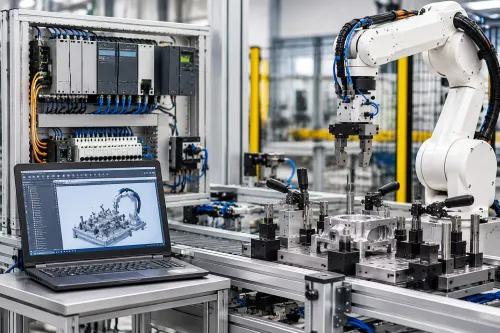

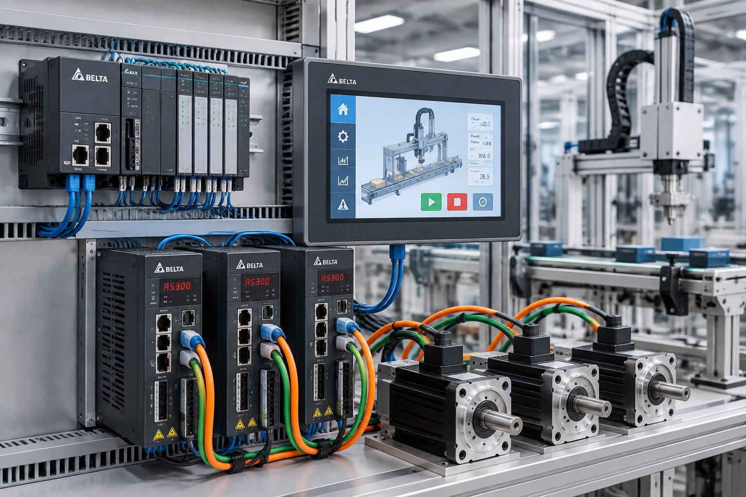
A successful project starts before anyone writes PLC code: the machine sequence, I/O, motor load, safety circuit and communication method must fit together. By the end, you will know how engineers select the hardware, program motion, build diagnostic screens, connect SCADA and test the system under real operating conditions.
Key takeaways
- Define sequence, cycle time, axis limits and safety before selecting hardware.
- Map PLC motion commands to servo-drive feedback and fault handling.
- Commission homing, tuning, positioning accuracy and recovery from faults.
- Validate HMI tags, SCADA data, interlocks and production-ready safety tests.
What is defined before Delta hardware is selected?
The first stage converts the machine requirement into a control architecture before any Delta hardware is selected. Document the operating sequence, cycle time, axes, travel limits, positioning accuracy, motor load, homing method, safety functions and production-data requirements.
That specification becomes an I/O list covering digital inputs and outputs, analogue channels, encoder feedback, drive signals, remote I/O and safety devices. Record network addresses, panel clearances, protective earth, enclosure requirements and the supervisory or SCADA layer before fabrication begins.
| Selection check | What to verify | Failure if ignored |
|---|---|---|
| PLC | CPU capacity, program and data memory, scan-time demand, and I/O count | Slow response or insufficient expansion |
| HMI | Screen size, tag capacity and diagnostic visibility | Crowded screens and poor fault finding |
| Servo system | Drive current and power ratings, motor inertia, encoder type and positioning accuracy | Overload, instability or inaccurate moves |
| Mechanical load | Motor, coupling, belt or ballscrew, braking resistor and travel limits | Excess heat, vibration or premature wear |
| Panel | Input protection, ventilation and heat load | Trips, shortened component life or thermal shutdown |
Check the PLC, HMI and servo drive as one system. Matching brands does not guarantee a suitable motion interface; the drive model and PLC motion capability determine the communications method and timing.
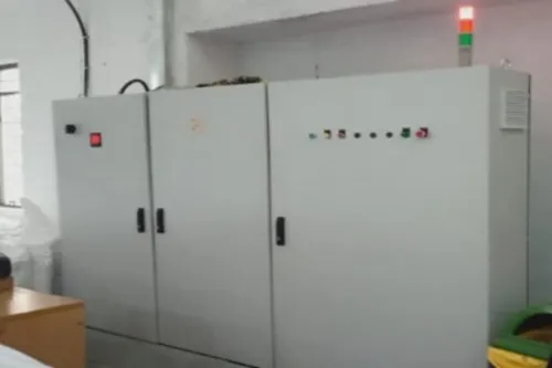
For a Delta PLC system installation in Dubai, also verify motor-power separation from encoder, analogue and communication wiring, protective-earth bonding, enclosure protection, airflow and maintenance access. These records define the architecture before purchasing and prevent a wiring, thermal or compatibility problem from becoming an expensive panel rework.
How do the PLC, HMI and servo drive exchange motion commands?
A motion command normally starts at the HMI, passes to the PLC, and reaches the servo drive through an interface selected for the drive model, PLC motion features and required positioning performance. The HMI should not control the drive directly; the PLC validates the command, applies permissives and manages feedback.
1. Use high-speed pulse and direction for a straightforward axis when the PLC can generate the required pulse frequency. Specify pulse polarity, direction polarity, electronic gearing, acceleration, deceleration, maximum travel and position limits. An incorrect polarity or gear ratio can send the axis in the wrong direction or produce the wrong distance.
2. Use CANopen or EtherCAT when the selected PLC and drive support the required cyclic updates, status words and coordinated-axis functions. This fieldbus path suits tighter synchronisation, interpolation and multi-axis control; confirm the supported cycle time before selecting it.
3. Use Modbus RTU over RS-485 or Modbus TCP for parameter access, status monitoring and simpler command structures. Modbus is not automatically equivalent to cyclic motion control, so a standard PLC scan fits sequenced moves only when timing and axis count remain within specification.
4. Require a motion controller or PLC with dedicated motion functions for coordinated interpolation, tightly synchronised camming, high-speed registration or deterministic synchronisation. During Delta PLC HMI servo integration in Dubai, document every address, register, data type, scale factor, byte order, timeout, retry rule and writable-register owner.
What does servo programming and commissioning involve?
Servo programming starts by setting drive and motor parameters, selecting the encoder, and defining electronic gearing, acceleration, deceleration, speed and torque limits, plus the following-error threshold. The PLC sequence then manages servo enable, alarm reset, jog mode, absolute or relative moves, homing, in-position confirmation and emergency-stop behaviour.
1. Define homing before moving the axis. Record the sensor or encoder-index method, search direction, search and creep speeds, offset, permitted travel, timeout and response when the home switch is already active. Do not assume the encoder position remains valid after power-up.
2. Tune with the installed coupling, belt or ballscrew, mechanical load and operating speed. Check inertia mismatch, backlash, compliance and friction before changing gain. Excessive gain causes hunting, resonance and overshoot; insufficient gain causes lag. A notch or damping filter, or a mechanical correction, is safer than continually increasing gain.
3. Commission in this order: verify incoming power, protective earth, safety chain and emergency stop; test PLC I/O; establish PLC-to-drive communication; jog at low speed; home the axis; then run automatic motion. This sequence separates wiring, parameter, communication and mechanical faults.
4. Separate motor and encoder cables from analogue and communication wiring, bond protective earth, and verify drive, motor, encoder and braking-resistor compatibility. If the drive provides Safe Torque Off, wire STO and its reset behaviour into the safety circuit, not a normal PLC bit.
For Delta servo programming in Dubai, IkodeAutomation |08048033508 can review motion parameters, safety evidence and fault recovery records so commissioning does not become a screen-building exercise.
Related products
 | Component Sales and Services Delta Industrial Automation Ikodeautomation is one of the best Delta Industrial Automation solution providers, offering Delta PLC, HMI, Servo, SCADA, AC Drives and complete... View product → |
 | Industrial Automation Solutions & System Integration HMI Programming Services Ikodeautomation is one of the best HMI programming and industrial automation solution providers, offering professional HMI development and PLC-HMI... View product → |
How are operator screens, tags and SCADA data made trustworthy?
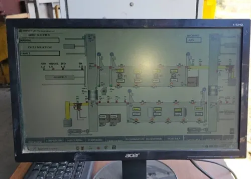
Machine states, not decorative graphics, should determine the HMI structure. Give operators separate manual and automatic modes, guarded jog controls, recipe values, alarm history, servo status, actual and commanded position, speed, torque, homing state and maintenance diagnostics.
Validate every recipe in the PLC for data type, range, machine state and interdependent values. HMI limits alone are not protection: another client or an offline download can bypass them. Separate operator setpoints from machine limits and engineering constants.
Use a shared tag map that assigns each command bit, feedback value, status word and alarm code to one named machine function. Document consistent names, engineering units, signed or unsigned definitions, scaling, device addresses, byte and word order, timeouts and ownership of writable values.
A diagnostic screen must identify the fault, not merely display “Servo Fault.”
| Condition | HMI indication | What it distinguishes |
|---|---|---|
| Servo inhibit | Servo-on permission absent | Enable or permissive problem |
| Following error | Position error exceeds threshold | Lag, tuning or mechanical fault |
| Overtravel | Positive or negative limit active | Travel-limit interruption |
| Encoder fault | Feedback alarm code | Encoder or cable failure |
| Safety interruption | Safety chain or STO open | Guard or emergency-stop action |
| Communication loss | Device, register and stale-data status | Network or mapping failure |
Delta SCADA integration in Dubai normally places SCADA above the machine PLC. Through a supported driver such as Modbus TCP, it reads selected modes, alarms, totals, recipes and process values; the PLC retains sequencing, permissives and safety logic. Add timestamps or sequence-of-events handling, communication quality, stale-data detection and interruption recovery.
One Communication OK bit cannot identify a failed device or register.
How is the completed system proved safe and production-ready?
Acceptance testing proves safe behaviour during faults, recovery and environmental stress, not just a successful automatic cycle. Verify incoming power, protective earth, input protection, drive-motor-encoder compatibility, panel ventilation, clearances and heat dissipation before production trials.
For Delta industrial automation in Dubai, check ambient temperature, dust, restricted airflow, enclosure protection and access for cleaning filters or servicing fans. Poor cooling can reduce drive and power-supply margins. Confirm motor cables are separated from encoder, analogue and communication wiring.
Run this fault-and-recovery checklist:
- Power-cycle the system and verify a controlled restart with no unexpected motion.
- Disconnect and restore PLC-to-drive communication; record the alarm and recovery state.
- Simulate encoder failure, overtravel and drive alarm reset.
- Activate the emergency stop during motion and open the guard.
- Interrupt homing, then confirm the axis cannot resume from an unsafe position.
- Enter an invalid recipe value and verify PLC-side validation rejects it.
- Stop a cycle and test the defined restart sequence, including required operator authority.
- Record the expected result, actual result, alarm text, reset authority and recovery state for every test.
An HMI Stop command is not the safety function. Emergency stopping, guard interlocking and prevention of unexpected restart must follow the risk assessment and selected safety architecture, including tested Safe Torque Off wiring where provided.
The handover file must contain electrical drawings, I/O lists, network topology, register maps, PLC and HMI backups, servo parameters, tuning records, safety-test results, alarm lists and operator instructions. These records let maintenance separate wiring, parameter, mechanical and program faults.
Frequently asked questions
What must be defined before selecting Delta PLC, HMI and servo hardware?
Document the operating sequence, cycle time, axes, travel limits, positioning accuracy, motor load, homing method, safety functions and production-data requirements.
How do a Delta PLC, HMI and servo drive exchange motion commands?
The PLC executes the motion sequence, sends position or speed commands to the servo drive, and receives feedback such as position, status and faults. The HMI provides operator commands and displays machine states.
What does Delta servo programming and commissioning involve?
Set motor and drive parameters, configure homing, limits and motion profiles, tune the axis, verify positioning accuracy, and test alarms and recovery procedures.
How are HMI tags and SCADA data made trustworthy?
Use a documented tag list, consistent naming, defined data types, clear alarm states and tested PLC-to-HMI mappings. Confirm that SCADA values match live machine conditions and recorded events.
How is a completed Delta automation system proved safe and production-ready?
Test emergency stops, guards, interlocks, travel limits, fault responses, restart behaviour, cycle performance and data logging under controlled production conditions before handover.
Related products
 | Industrial Automation Solutions & System Integration PLC Programming Services Professional PLC Programming & Automation Solutions - Ikode Automation is one of the best PLC programming and industrial automation solution... View product → |
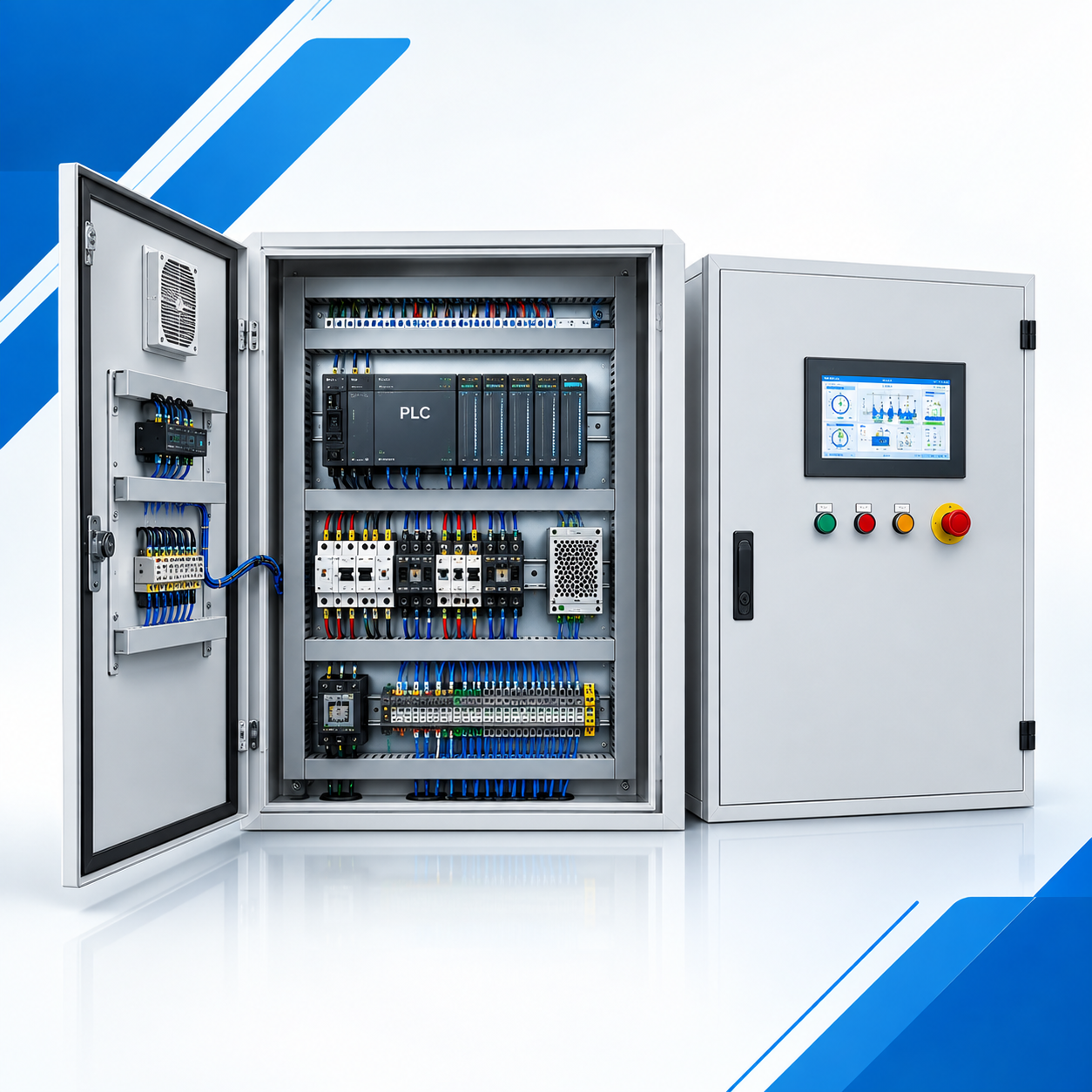 | Industrial Automation Solutions & System Integration PLC Control Panel Manufacturer & Automation Solutions Professional PLC Control Panel Design & Automation Solutions -Ikodeautomation provides professional PLC Control Panel design, manufacturing,... View product → |
 | Industrial Automation Solutions & System Integration Industrial Automation Component Sales Reliable Automation Components. Trusted Industrial Solutions.Ikodeautomation is one of the leading industrial automation component sellers and... View product → |