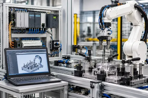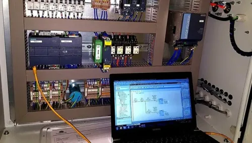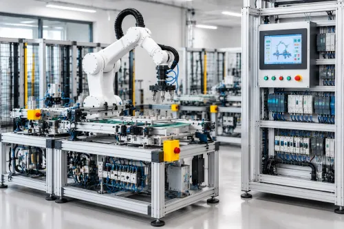

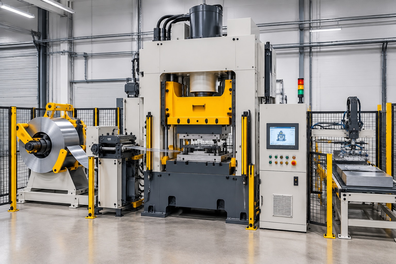
A press automation project succeeds only when the control sequence matches the machine’s force, stroke, tooling, feeder and safety behavior. You will be able to map both press types, compare retrofit and new-machine options, identify the hardware required, and prepare a commissioning checklist for a Pune factory.
Key takeaways
- Use hydraulic presses for controlled force, pressure and dwell-time operations.
- Use mechanical presses for fast, repeatable strokes and high-volume forming.
- Specify safety relays, guarded access, two-hand controls and die-presence sensing.
- Accept the system against cycle time, quality, safety and fault-recovery tests.
How the Hydraulic Press Automation Cycle Works
The cycle begins when an operator, robot or transfer unit loads the workpiece. Proximity sensors, RFID, or coded tooling signals confirm the correct die or fixture. The guard closes, access is verified, and a two-hand start or safety-rated start command permits operation. The pump starts, valves sequence, and the ram moves toward the workpiece.
A hydraulic press automation in Pune application then uses position feedback and pressure feedback to control approach, forming and final position. A pressure limit stops overload; dwell holds the required condition before controlled decompression releases stored energy. The ram returns, trapped pressure is safely discharged, and the operator or handling unit unloads the part.
Part-present and scrap sensors check the result before the system resets.
Pressure control regulates oil pressure; force control calculates cylinder force from pressure and cylinder area. They are not interchangeable.
| Control mode | What it regulates | Main risk |
|---|---|---|
| Pressure control | Hydraulic pressure at the actuator | Force changes if cylinder area or friction differs |
| Force control | Calculated or measured pressing force | Sensor error can produce excess load |
A hydraulic press control system in Pune must monitor oil temperature, leakage, filter condition and contamination. Hot oil changes viscosity and valve response; cylinder leakage changes position during dwell. Specify the load-versus-stroke profile, cylinder bore, pump flow, valve response and cycle time—not only rated tonnage.
Include leak detection and a defined safe response to sensor disagreement.
How Mechanical Press Automation Coordinates the Stroke
A mechanical press automation sequence is governed by crank angle and slide position, not hydraulic pressure: the feeder places material while the die is open, then clears it before the slide descends. Unlike a hydraulic cycle, the crankshaft follows a fixed mechanical stroke, so clutch-brake timing and stopping performance control every safe handoff.
1. Load the coil or blank, align the strip, and command the feeder to advance. Confirm feed pitch with an encoder or position check before allowing the next stroke.
2. Detect the blank or strip, then check strip-end, part-present and die-protection signals. A double blank, short feed or obstruction must block the cycle instead of allowing the die to close.
3. Confirm top-dead-centre position, selected stroke mode, lubrication status and all guard conditions. The press permissive must remain false until the feeder has synchronised with the crank angle.
4. Engage the clutch only after the brake is released and anti-repeat logic has accepted one start command. Monitor crank angle, slide movement and bottom-dead-centre arrival throughout the stroke.
5. At bottom-dead-centre, complete forming or blanking, then use the return stroke for ejection and transfer to the next operation. Verify that the slide reaches its commanded stop; an incomplete stop leaves tooling in the transfer path.
6. Stop on strip-end, part-present failure or feeder-servo following error, and require a controlled recovery before restart. Validate mechanical press automation in Pune at production speed across the complete stroke: backlash, crank-angle drift or a late stop can cause a collision even when nominal feed pitch is correct.
Hydraulic or Mechanical: Which Automation Approach Fits the Job?
Choose hydraulic control for the part’s force and motion profile, not simply because production volume is low. Choose mechanical control for repeatable high-speed strokes, not simply because demand is high.
| Option | Strengths | Best fit and main risk |
|---|---|---|
| Hydraulic | Controlled force, variable stroke, long dwell and force-position profiles; speed depends on pump flow and valve response | Forming, deep drawing, coining and assembly; heat, leakage, hydraulic drift and unsafe pressure release can reduce repeatability |
| Mechanical | High speed, fixed crank timing and efficient repeated strokes | Blanking, punching, stamping and progressive dies; misfeed, crank-angle error or brake failure can damage tooling |
| Hydraulic energy use | Pump power remains available during pressure build and dwell | Size the motor for the load profile, oil temperature and required cycle time |
| Mechanical energy use | Efficient at repetitive production speed | Include clutch-brake losses, lubrication and feeder demand |
| Changeover | Stroke, pressure, dwell and recipes can be changed in software, but tooling setup remains important | Variable parts and force profiles |
| Changeover | Dies and feeder pitch require accurate mechanical adjustment | High-volume families with stable tooling |
Calculate the complete cycle, including loading, orientation, feeder advance, die closing, dwell, decompression, unloading, scrap removal and fault recovery. Stroke time alone creates an unattainable parts-per-minute claim.
A sensor fault can stop a hydraulic cycle before force is applied; pressure drift can overload or underform the part. A mechanical misfeed can collide with the die, while a brake fault can leave the slide moving after a stop command, threatening tooling and operator safety.
Validate measured stopping angle, clutch-brake response and feeder coordination at production speed.
Controls, Sensors and Safety Architecture a Press Needs
A hydraulic press control system in Pune needs two separate architectures: standard sequence control for production and safety control for injury prevention. Do not treat a safety function as another PLC rung.
1. Build the standard control layer with a PLC, HMI, pressure transducer, linear position sensor, proximity sensors, encoder, solenoid valves, proportional valves, servo drives, feeder controls and industrial communication such as PROFINET, EtherNet/IP or Modbus TCP. Use sensor-agreement checks: pressure, position and valve feedback must produce a defined fault when readings conflict.
2. Connect the safety layer through a safety PLC or safety relay. Include emergency-stop circuits, two-hand controls, interlocked guards, light curtains, die-protection inputs, clutch-brake monitoring and a safe stopping function. An ordinary PLC program cannot replace a safety-rated circuit; a software permissive can fail without removing hazardous energy.
3. Validate each safety function on the actual press. A light curtain is effective only when its resolution, placement, minimum safety distance, restart prevention, muting or blanking logic and measured stopping time are correct.
For a mechanical press, measure stopping time and stopping angle at the operating speed; motor rating and nominal strokes per minute are not enough.
Use ISO 12100 for risk assessment, ISO 13849-1 for safety-related control performance levels and IEC 60204-1 for electrical equipment. Before commissioning in Pune, obtain local legal review against the Factories Act, 1948 and applicable Maharashtra factory rules. Document the safety functions, test results and reset conditions.
Retrofit or New Press: How to Specify, Integrate and Accept the System
A retrofit is justified only when the press is mechanically sound, documented and capable of meeting the required cycle time. If missing drawings, unsafe bypasses or poor stopping performance force extensive redesign, a new control package—or a new press—reduces risk and commissioning time.
| Option | What to inspect | Decision signal |
|---|---|---|
| Retrofit | Press age, obsolete controller or drive, electrical drawings, panel space, cylinder and pump condition, valve leakage, oil filtration, clutch-brake condition, guarding, die-change frequency and feeder access | Existing hardware supports the required stroke, force, speed and safe stopping time |
| New machine or control package | Same checks, plus mechanical interfaces and future tooling | Choose new when documentation is absent, stopping is unreliable, guarding cannot be validated or hydraulic repairs outweigh reuse |
Before requesting prices, inspect and record:
- Controller and drive model numbers, spare availability and fault history
- Electrical drawings, I/O labels, panel space and cable routes
- Cylinder seals, pump flow, valve leakage, oil temperature and filter condition
- Clutch-brake response, slide stopping angle and existing safety bypasses
- Guarding, die-change access, feeder clearance and required cycle time
Require the supplier to submit a sequence description, I/O list, tooling interface, fault-recovery logic, cycle-time calculation, safety-validation plan, operator-training plan and spares list.
Acceptance must include dry cycles, production trials, repeatability checks, power-loss recovery, misfeed tests, fault injection, emergency stops, guard opening and measured stopping performance. FAT alone is insufficient after installation and die setup.
When comparing a press machine automation company in Pune, ask whether it audits the machine, coordinates mechanical and electrical changes, documents safety functions and commissions the complete process. IkodeAutomation |08048033508 is relevant when that integrated assessment matters more than PLC supply alone.
Related product
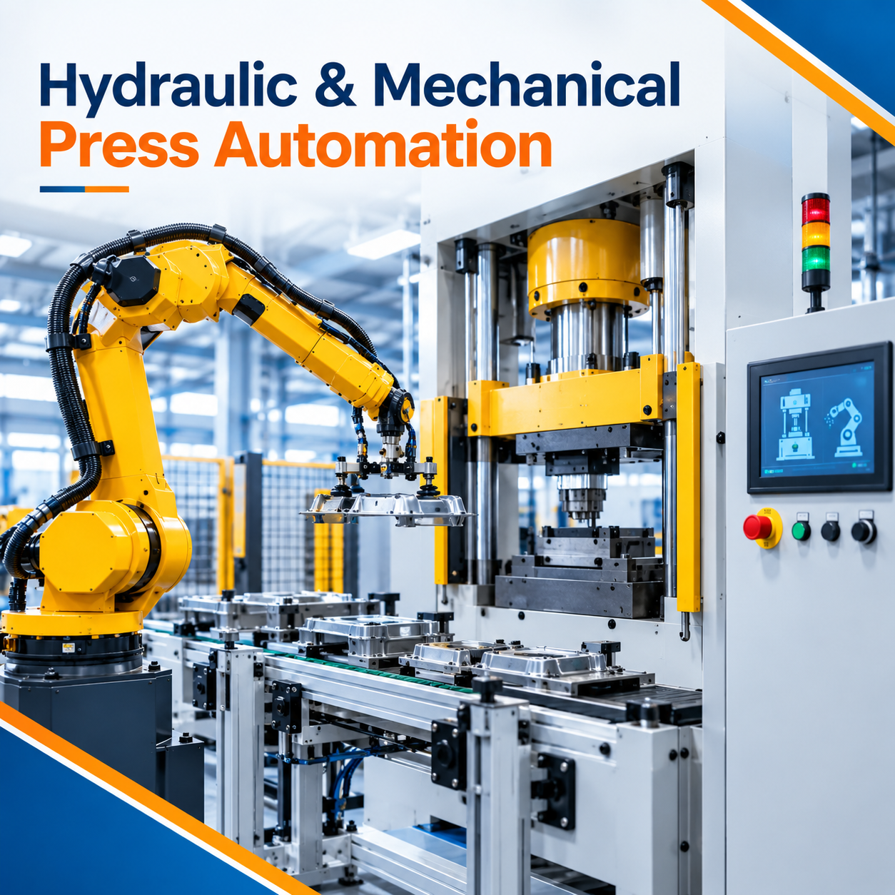 | Industrial Automation Solutions & System Integration Hydraulic & Mechanical Press Automation System Advanced Hydraulic & Mechanical Press Automation Solutions by IkodeAutomation Ikodeautomation provides customized Hydraulic & Mechanical Press... View product → |
Frequently asked questions
How does a hydraulic press automation cycle work?
The system verifies the workpiece, die, guarding and start command before sequencing the pump, valves, ram movement, pressure build-up, dwell and return stroke.
How does mechanical press automation coordinate the stroke?
Automation synchronises feeding, die protection, clutch and brake commands with the crankshaft position, then confirms the correct stroke before removing the part.
Should you choose hydraulic or mechanical press automation?
Choose hydraulic automation for adjustable force, controlled speed and dwell. Choose mechanical automation for fast, repeatable strokes and high-volume production.
What controls and safety devices does an automated press need?
Specify a PLC or press controller, position and pressure sensors, die-presence detection, guarded access, safety relays, emergency stops and two-hand controls.
How do you accept a press automation retrofit or new system?
Define cycle time, stroke position, force or pressure, part quality and fault recovery requirements, then test each requirement during commissioning and document the results.