
A painting cell is more than a robot: loading, fixturing, ventilation, paint delivery, flash-off, curing, inspection and safety controls all determine whether the line meets its promised takt and coating quality. By the end, you will be able to define the process, compare equipment architectures, specify the control and safety scope, and judge an integrator’s proposal before commissioning.
Key takeaways
- Map presentation, spraying, curing, inspection and records as one controlled process.
- Choose booth architecture and coating method together, not as separate purchases.
- Specify recipes, fixture identification and acceptance tests before selecting equipment.
- Review exhaust, solvent storage and waste controls with MPCB requirements early.
How painting automation fits the complete machine-builder process
Map the line as one controlled process, not as a robot surrounded by accessories. The machine-builder scope runs from part presentation and fixture identification through spraying, curing, inspection and production records; painting automation in Pune also requires early review of exhaust, solvent storage and waste obligations with the Maharashtra Pollution Control Board.
1. Load the part onto a fixture with a defined datum, orientation and grounding point. Verify the fixture or part ID before the cycle starts.
2. Transfer the fixture by conveyor, indexing table or overhead system, and confirm its position before booth entry. A shifted datum changes gun distance, angle and coverage.
3. Select the recipe by part variant and coating stage. Lock paint viscosity, flow rate, atomizing pressure, gun-to-part distance, robot speed and overlap to that recipe.
4. Interlock spraying with booth exhaust, door status, airflow and emergency circuits. Loss of extraction must stop atomization, not merely create an HMI alarm.
5. Apply primer, liquid topcoat or powder through the specified gun path, then control flash-off time and curing temperature. Record gun, pump and oven values.
6. Flush guns and hoses during colour changes, recording purge volume and changeover time. Dead volume and an unsuitable colour sequence create waste and cross-contamination.
7. Unload only after cure confirmation, then inspect film thickness, colour, gloss, adhesion or visible defects against agreed limits.
8. Store recipe identity, batch, alarms, operator actions and inspection results for traceability. Accept the cell with representative production parts, not a dry-cycle demonstration.
Choose the cell architecture and coating method together
Match the cell to the part’s geometry, material and takt time before choosing the spray equipment. A six-axis robot suits complex surfaces, frequent variant changes and controlled gun angles; a reciprocating machine suits high-volume parts with consistent profiles; fixed guns suit simple parts that pass through a defined presentation path.
| Architecture | Coating method | Best fit | Main limitation |
|---|---|---|---|
| Six-axis robot | Air spray or electrostatic liquid | Complex parts, multiple faces, primer and topcoat variants | Needs stable fixtures, grounded parts and validated gun distance |
| Reciprocator | Airless, air-assisted airless or electrostatic liquid | High-volume panels, cabinets and repeated profiles | Poor choice for deep recesses or frequent geometry changes |
| Fixed-gun machine | Air spray, airless or powder | Simple shapes with predictable orientation | Coverage depends heavily on fixture and part presentation |
| Robot or reciprocator | Powder coating | Durable metal parts with compatible cure temperature | Requires powder recovery, grounding and an oven matched to the substrate |
| Manual booth with automated controls | Liquid spray | Low volume, oversized parts or frequent one-off jobs | Operator variation remains a quality risk |
Air spray gives control over finish and detail; airless deposits material faster but demands careful pressure and viscosity control. Electrostatic liquid or powder improves transfer on grounded metal, but recessed areas can suffer from Faraday-cage effects.
The automated painting system integrator must validate fixture datum, gun angle, overlap, speed, atomizing pressure, viscosity and grounding on representative production parts. Industrial painting machine automation is incomplete if it covers only the robot: include booth exhaust, paint delivery, curing, flushing, safety circuits and inspection criteria.
For two-component paint, also specify ratio control, pot life, hose residence time and automatic cleaning.
Define part presentation, recipes and process controls before selecting equipment
Fix the engineering data before choosing a robot, conveyor or spray gun. Record each part family’s dimensions, material, coating zones, masking areas, datum points, orientation, fixture location and allowable variation. A repeatable robot path cannot correct a part presented 8 mm off datum or rotated on an inconsistent jig.
1. Define presentation: assign a fixture ID, locating-pin scheme, clamp confirmation, part orientation and entry position. Measure gun-to-part distance and gun angle at every critical surface, including recesses, edges and shadowed areas.
2. Define the recipe: link part or batch identity to primer or topcoat, colour, number of passes, path speed, overlap, trigger timing, atomizing pressure, fluid flow, electrostatic voltage where used, flash-off time and cure temperature.
3. Define process limits: set acceptable ranges for paint viscosity, booth airflow, grounding resistance, conveyor speed, pump pressure and oven temperature. Interlock spraying when exhaust proving, fixture confirmation, paint pressure or grounding fails; an HMI alarm alone will not prevent a defective part.
4. Define evidence: store recipe identity, operator actions, alarms, parameter changes and coating results against the part or batch. Validate coverage, dry-film thickness, gloss and adhesion on representative production parts, not on a dry robot cycle.
For painting automation for system integrator in Pune, this specification also fixes the interfaces for loading, PLC and HMI data, gun flushing, inspection and curing. It prevents a common failure: selecting equipment first, then discovering that one cell needs different fixtures, hazardous-area components or control logic for every variant.
Build ventilation, hazardous-area and thermal safety into the design
A failed exhaust fan must stop atomization, not merely trigger an HMI alarm.
For painting booth automation in Pune, size mechanical ventilation against the booth geometry, coating chemistry and applicable code; OSHA rules use 100 ft/min average velocity across the open face of many spray booths, while the legally applicable Indian design basis requires separate confirmation.
Provide make-up air, filtered supply air, grounded equipment, suitable compressed air, and controlled paint and solvent delivery.
Use the safety design to verify:
- Hazardous-area classification covers vapour and combustible-material risks beyond the booth interior when ventilation, paint chemistry or construction extends the boundary. Select motors, sensors, lighting, junction boxes, robot dress packs and panels to that classification.
- Spray enable requires proven exhaust airflow, closed access doors and acceptable paint pressure. Define safe states for robot motion, pumps, atomization, heated hoses, solvent flushing and ventilation; a stopped robot can leave other hazards active.
- Flash-off zones and ovens need purge timing, airflow proving, burner-management hardware, temperature control, independent over-temperature protection and solvent-vapour interlocks. A PLC output to a heater is not burner safety.
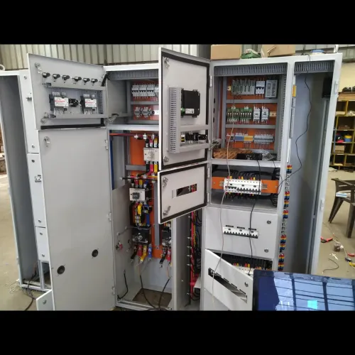
- Include booth extraction, gun cleaning, filter access, fire protection, emergency stops and maintenance isolation in the utility layout.
Clarify the Maharashtra Pollution Control Board approval boundary before construction. Volatile-organic-compound emissions, paint and solvent storage, sludge, used filters and contaminated wipes create separate consent or waste-management duties; extraction alone does not prove compliance. Capture airflow, pressure, temperature, alarm and emission-related records for commissioning and inspections.
Evaluate the integrator by interfaces, acceptance tests and production evidence
Compare a painting automation system integrator for machine builders in Pune by the interfaces it owns, the evidence it produces, and the tests it accepts—not by robot brand or quoted cycle time. The robot is only one part of the line.
| Interface to verify | Evidence to request | Failure exposed |
|---|---|---|
| Part loading, datum and fixture ID | Loaded-part repeatability records and fixture drawings | Coverage shifts between batches |
| Booth exhaust and spray enable | Hardwired interlock test showing atomization stops on exhaust loss | Paint continues during unsafe airflow |
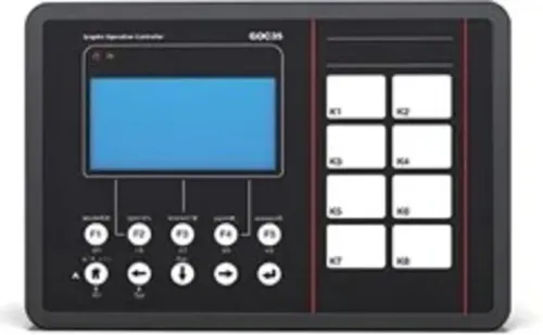
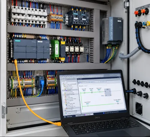
| PLC, HMI, recipes and production data | I/O list, alarm history, recipe revision control and sample reports | Operators cannot trace defects |
| Paint delivery, flushing and colour change | Hose dead-volume calculation, purge volume and timed colour-change trial | Waste and cross-contamination exceed the estimate |
| Curing and inspection | Temperature logs, conveyor-speed records and coating measurements | Parts leave under-cured or inconsistently coated |
Require a factory acceptance test using representative production parts, actual fixtures, each coating stage and the planned colour sequence. Define pass criteria before the test: dry-film thickness range, adhesion result, gloss or colour tolerance, defect limit, cure profile, changeover time and first-pass yield. A dry robot demonstration proves almost none of these.
For painting automation in Pune, also request the hazardous-area classification, exhaust airflow test, safety-circuit validation and Maharashtra Pollution Control Board approval boundary. Confirm that panels, sensors, lighting and robot dress packs match the classification.
IkodeAutomation |08048033508 is worth evaluating only through this evidence: ask it to separate its scope for jig and servo automation, controls, booth interfaces, commissioning and production support rather than accepting “complete automation” as a deliverable.
Related product
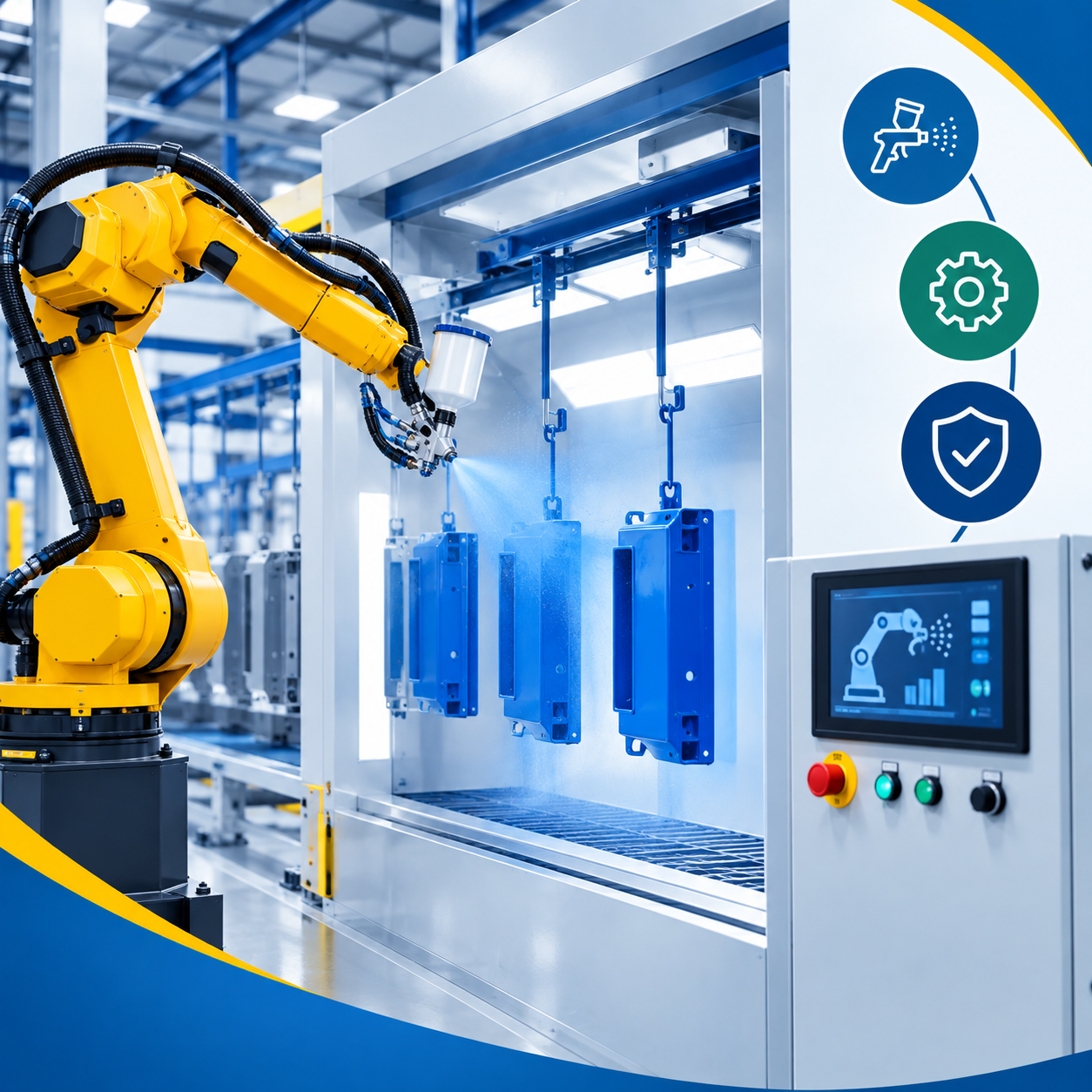 | Industrial Automation Solutions & System Integration Advanced Painting Automation Systems for Modern Industries,Painting processes in modern manufacturing require precision, consistency, speed, and... View product → |
Frequently asked questions
How does painting automation fit a machine-builder project?
Treat it as one controlled process from part presentation and fixture identification through spraying, curing, inspection and production records.
How should you choose a painting cell architecture?
Choose the cell architecture and coating method together, then align robot reach, booth design, curing, exhaust and material handling.
What must you define before selecting painting equipment?
Define part presentation, fixture identification, recipes, spray parameters, curing requirements, inspection points and production records.
How do you evaluate an automated painting system integrator?
Check how the integrator manages interfaces, hazardous-area and thermal safety, acceptance tests, documentation and evidence from comparable production systems.