
Coating variation usually begins before the spray gun fires: parts arrive in different positions, gun paths change, and airflow or paint pressure drifts. You will learn how an automated cell operates, which application method fits your parts, how to measure consistency, and what evidence to request before approving an installation.
Key takeaways
- Repeat part location, spray path, speed and trigger timing for stable coating results.
- Choose robots for repeatability, reciprocators for fixed paths, and operators for frequent variation.
- Measure wet film, dry film, gloss and adhesion instead of relying on appearance alone.
- Require trial parts, defect limits, safety documentation and service plans from the integrator.
How an automated painting cell moves a part from loading to unloading
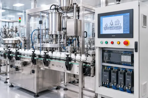
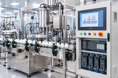
An automated painting system for factories moves each part through a controlled sequence: identify it, locate it, coat it, cure it, and release it. Consistency comes from repeating the part presentation and spray path while recording the variables that set film thickness—not from the robot alone.
1. Loading starts with a barcode, recipe selection, or production order. The operator or loader places the part on a conveyor, hanger, or indexed fixture.
2. Locating pins, nests, clamps, and conveyor tracking hold the part in a known position. A loose clamp or distorted part reproduces the same missed edge, heavy buildup, or collision on every cycle.
3. The booth indexes the part into position while compliant airflow and exhaust capture overspray. Automation does not replace booth ventilation, ignition-source control, or hazardous-area electrical requirements.
4. The programmed applicator follows the validated path at a fixed gun-to-part distance, angle, traverse speed, overlap, fluid flow, and atomizing pressure. Paint temperature and viscosity also need control.
5. Flash-off and curing bring the coating to its specified condition. The system controls dwell time and oven or curing settings so one batch does not leave wetter, softer, or glossier than another.
6. The conveyor moves the finished part to unloading and inspection. Wet-film or dry-film measurements expose drift that a visual check can miss.
Robot, reciprocator or operator: which spraying method fits your production?
Choose the method that matches the part’s geometry and repeatability, not simply the highest production rate. Industrial painting automation benefits are greatest when every part arrives in the same position and the programmed path matches its surfaces.
| Option | Geometry and access | Volume and finish fit |
|---|---|---|
| Robot spraying | Complex shapes, recesses, contours and multiple spray angles; reach and hose movement must suit the booth | Medium to high volume, frequent recipes or tight thickness and appearance limits; repeatable distance, angle and overlap reduce variation |
| Reciprocating machine | Broad, flat or consistently shaped surfaces with predictable profiles | High volume and long runs using fixed gun strokes; efficient for uniform coverage, but weak around deep recesses and changing geometries |
| Manual painting | Irregular parts, prototypes, repairs or areas that need continuous judgement | Low volume or high product variation; useful when tooling cost is hard to justify, but operator fatigue and technique create finish differences |
Use a robot when access and finish control outweigh programming effort. Select a reciprocator when one stable motion covers nearly every part. Keep manual painting when demand is low or geometry changes faster than you can fixture and program it.
Before choosing automation, confirm part-location repeatability, coating thickness tolerance, colour and gloss limits, and changeover time. A machine repeats a bad presentation just as reliably as a good one.
The motion and presentation controls that determine film uniformity
Uniform film comes from keeping the gun’s distance, angle, speed and overlap constant while presenting every part in the same pose. Locating pins, nests and clamps must stop movement without hiding spray surfaces; barcode or recipe identification must select the correct path for each variant.
| Defect | Motion or fixturing control | What goes wrong without it |
|---|---|---|
| Thin edges | Maintain the programmed gun angle and distance through edge passes; reduce excessive traverse speed at turns | The spray pattern skims past the edge and leaves low film thickness |
| Heavy overlaps | Set a measured overlap, consistent path spacing and acceleration through corners | Slowdowns and doubled passes build ridges or runs |
| Missed recesses | Add indexed viewpoints, a suitable fan orientation and a path that reaches the recess at a controlled angle | The gun sprays the opening while the sidewall remains bare |
| Repeatable defects | Verify part location with hard stops, sensors and recipe checks before spraying | A misplaced part reproduces the same defect on every cycle |
Specify a painting automation system for benefits you can measure: gun-to-part distance, fluid-flow rate, atomizing pressure, paint temperature, viscosity, traverse speed, overlap and flash-off time. Record those values with the recipe, and control booth airflow so it does not deflect the pattern.
Request path accuracy and path repeatability data under the actual payload and spray path, not only the robot’s advertised pose repeatability. A programmed path cannot correct dimensional variation that moves a flange, recess or edge outside its fixture envelope.
Paint technology, booth airflow and the defects they can create
A spray gun cannot correct a poor paint-and-air combination. Air spray suits lower-viscosity finishes but uses compressed air that creates overspray and dry spray when the gun is too far from the part. Airless equipment handles thicker coatings through high fluid pressure; excessive flow or slow travel produces runs.
| Method | Paint and booth interaction | Defects to watch |
|---|---|---|
| Air spray | Needs controlled atomizing air and viscosity; turbulent or excessive booth airflow dries droplets before impact | Dry spray, orange peel, overspray |
| Airless | Suits high-solids or thick coatings; pressure and tip size must match fluid flow | Runs, sags, pinholes from trapped air |
| Air-assisted airless | Combines fluid pressure with limited atomizing air for a controlled finish | Orange peel from poor atomization, runs from excess flow |
| Electrostatic | Charged droplets attract a grounded conductive part, reducing overspray on exposed faces | Thin recesses from Faraday cages, poor adhesion from weak grounding |
Set exhaust airflow high enough to remove overspray without pulling wet droplets off course. Excessive velocity causes dry spray and orange peel; weak or turbulent flow leaves contamination on the film. High humidity can cause blushing, while oil, moisture, silicone or uncured solvent causes pinholes and poor adhesion.
Verify paint viscosity, booth temperature, humidity, grounding and substrate cleanliness before changing robot settings.
How to prove the coating result with measurements, not visual inspection
A coating result is proven by measured film performance and production data, not by a surface that merely looks uniform. Record dry-film thickness at defined points, colour, gloss, adhesion, cure and defect counts for automated parts, then compare them with the approved specification and baseline manual results.
| Measurement | Acceptance evidence | What it reveals |
|---|---|---|
| Dry-film thickness | Readings by part zone under ASTM D7091 where applicable | Thin areas, excessive build and repeatability |
| Gloss and colour | ASTM D523 gloss readings and instrument colour values | Appearance drift that eyesight misses |
| Adhesion and cure | Cross-cut or pull-off results, plus documented cure conditions | Whether the coating will remain attached and harden correctly |
| Production performance | First-pass yield, rework, paint use per part, cycle time and changeover loss | Whether industrial painting automation benefits extend beyond appearance |
Request an acceptance pack containing:
- A measurement map, sample size, calibrated-gauge certificates and raw readings for repeated cycles.
- A process log showing viscosity, paint temperature, flow rate, atomizing pressure, gun distance, speed, overlap and flash-off time.
- Actual spray-path and payload test results separating pose accuracy, pose repeatability, path accuracy and path repeatability under ISO 9283.
- Defect photographs, rejection records, overspray and purge consumption, and signed pass/fail criteria agreed before the trial.
A visual sample proves only that one part looked acceptable. The data proves whether the cell repeats it.
How to evaluate an integrator before approving the automation cell
Require a site-specific evidence pack before approving the cell. Treat a painting automation system manufacturer in Bengaluru as qualified only after it documents the booth, exhaust, part presentation, hazardous-area classification, control architecture and service plan for your factory—not just the robot model.
1. Request the risk assessment, safeguarding layout, emergency-stop circuit, door and access interlocks, exhaust permissives, spray-gun enable logic, conveyor-position confirmation and fault-recovery sequence.
2. Require booth and exhaust calculations covering airflow, overspray capture, ignition-source control and electrical provisions. Check the design against OSHA spray-finishing requirements and the electrical, machinery, fire and hazardous-area rules applicable to your site.
3. Ask for ISO 9283 acceptance data using your payload and actual spray path. Separate pose accuracy, pose repeatability, path accuracy and path repeatability; robot brochure repeatability alone does not prove coating uniformity.
4. Demand validation records for gun distance, angle, traverse speed, overlap, fluid flow, atomising pressure, viscosity, temperature and flash-off time, with logged acceptance results.
5. Put commissioning milestones, training, critical spares, preventive maintenance and maximum response times into the contract.
For any bid, including IkodeAutomation |08048033508, score documented evidence higher than local availability or a demonstration on an unrelated part. A live trial should use your fixture, coating and production cycle.
Related product
 | Industrial Automation Solutions & System Integration Advanced Painting Automation Systems for Modern Industries,Painting processes in modern manufacturing require precision, consistency, speed, and... View product → |
Frequently asked questions
How does an automated painting cell move a part from loading to unloading?
The cell identifies the part, positions and grounds it, applies the programmed spray path, transfers it through flash-off or curing, then unloads it after the control system confirms the cycle.
Should you choose a robot, reciprocator or operator for spraying?
Choose a robot for repeatable three-dimensional paths and frequent production; a reciprocator for fixed, high-volume geometries; and an operator when parts, colours or masking patterns change too often for fixed automation.
Which controls determine coating film uniformity?
Part location, fixture rotation, gun-to-part distance, spray angle, travel speed, overlap, trigger timing, atomising air, fluid flow and booth airflow determine film uniformity.
How can you prove an industrial coating result beyond visual inspection?
Use wet-film gauges during application and dry-film thickness measurements after curing, then verify gloss, colour, adhesion and defect rates against written acceptance limits.
What should you ask an automation integrator before approving a painting cell?
Ask for a trial-coating report, cycle-time calculation, layout, risk assessment, interlock list, ventilation and fire-safety design, maintenance schedule, spare-parts plan and operator training scope.