
A relay-controlled machine can gain diagnostics, recipe handling and better production visibility, but a rung-for-rung rewrite can change timing, restart behavior and safety performance. By the end, you will know whether to convert or replace the control system, what evidence to collect, how engineers rebuild undocumented logic, and how to test the finished machine.
Key takeaways
- Convert when the machine mechanics, guarding and process remain sound.
- Photograph wiring, label every device and collect drawings before redesign.
- Preserve emergency stops, interlocks and safe-state behaviour independently of PLC logic.
- Define timer, latch, recovery, testing and handover requirements before selecting the PLC.
Decide Whether the Existing Machine Is Worth Converting
Convert the existing relay control system when the machine mechanics, frame, guarding and production process remain sound, but obsolete relays, timers or unavailable components threaten uptime. A PLC can improve diagnostics and spare-part availability without forcing you to redesign the machine.
| Option | What it means | When it applies |
|---|---|---|
| Convert the controls | Replace relay coils, contactors, timers and control wiring with PLC logic while retaining suitable field devices and machine hardware | The electrical panel is repairable, the sequence is understood, and the required cycle, speed and capacity remain adequate |
| Replace the control system entirely | Redesign the control architecture, including PLC, HMI, drives, instrumentation and safety functions | The panel is corroded, wiring insulation is damaged, drawings are unreliable, spare parts are unavailable, or production requirements exceed the existing design |
| Replace the machine | Retire the equipment rather than modernise it | Mechanical wear, poor guarding, obsolete process capability or repeated downtime makes controls work a false economy |
Ask providers of relay logic to plc conversion services to define whether their scope covers field rewiring, drives, HMI programming, safety circuits, documentation and commissioning. “RLC” is not a fixed abbreviation in procurement documents, so do not approve a vague RLC-to-PLC proposal.
Do not treat emergency-stop or guard circuits as ordinary PLC inputs and outputs. Retain or redesign them with safety relays or a safety PLC, then validate the stopping function against the machine risk assessment. Require point-to-point checks, fault tests, power-cycle tests and an owner-approved production trial before accepting the conversion.
Collect the Machine Evidence Before Engineering Starts
A reliable quote needs evidence from the machine, not just its model number. Ask for the latest electrical drawings, terminal schedules, panel layout, motor list, component manuals, I/O voltage levels, and machine safety documentation, including emergency-stop and guard-circuit details.
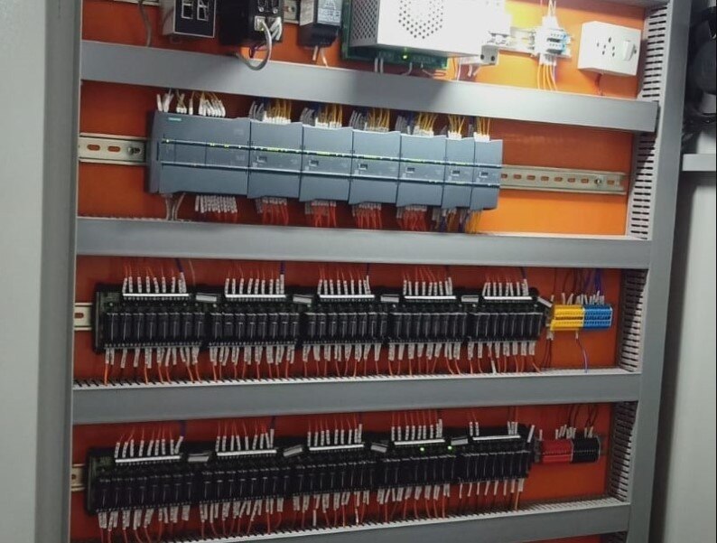
1. Photograph the closed and open control cabinet, both sides of every terminal strip, each relay and timer, wire numbers, fuses, contactors, overloads, PLCs, drives, nameplates, selector switches, sensors, and operator stations. Take close-ups that make labels readable and wide shots that show cable routing.
2. Mark each photograph with the machine area and cabinet reference. Include spare wires, unused terminals, damaged insulation, altered wiring, and components that differ from the drawings. These details expose undocumented modifications before engineering begins.
3. Write the operating sequence in plain language: startup conditions, automatic and manual modes, cycle times, step transitions, permissives, interlocks, alarms, normal stops, emergency stops, jam recovery, fault reset, power loss, and restart behaviour. State which outputs must remain off after a restart.
4. Provide the alarm list, recurring faults, production constraints, required downtime window, and any available backup program or maintenance records. Ask the relay logic conversion company to identify whether the scope includes panel rewiring, safety circuits, drives, instrumentation, HMI work, commissioning, and IEC 60204-1 verification.
Do not rely on “RLC to PLC conversion service” in a purchase request; define every deliverable. Missing evidence hides welded contacts, broken wires, failed timers, and auxiliary contacts used as feedback, producing a cheap quote that changes once the cabinet is opened.
Reverse-Engineer Relay Logic Without Losing Safety Functions
An undocumented panel is a wiring investigation, not a drawing exercise. Engineers photograph every terminal, wire number, relay contact and selector position, then trace each conductor against the machine’s actual response. They check coil voltage, contact state, overload operation and field-device operation with power isolated before performing controlled live tests.
The investigation produces a sequence and I/O register rather than a rung-by-rung copy:
- Identify each relay coil, timer, contactor, counter, overload auxiliary contact, selector switch, sensor and actuator.
- Record every normally open and normally closed contact, including auxiliary contacts that create permissives, latches or fault paths.
- Test each operating step, stop condition, jam response, alarm, reset and power-recovery behaviour.
- Mark terminal numbers, voltage levels, common returns and devices that share a circuit.
- Compare observed behaviour with operator instructions and the risk assessment.
Do not place an emergency-stop, guard switch or other safety-related stop function on ordinary PLC logic. Separate those circuits from production control and document whether the architecture needs dual-channel monitoring, safety relays or a safety PLC.
Establish the required performance level through risk assessment, then validate the completed function using ISO 13849-1 methods and applicable IEC 60204-1 requirements.
Map standard field devices into PLC input and output addresses, while safety inputs and outputs use the safety architecture. Preserve contactor feedback, overload trips and restart prevention as explicit diagnostics. This is how you convert relay control to PLC without turning an undocumented protective circuit into an unverified software assumption.
Recreate Timers, Latches and Recovery Behaviour Deliberately
A relay contact changes state as soon as its coil energises; a PLC sees the input during one scan, executes logic, then updates outputs. Copying seal-in circuits rung by rung can therefore change start timing, output feedback and interlock results.
1. Define every retained state. Convert a maintained relay or mechanical latch into a retentive bit, set/reset instruction or physical feedback requirement. Do not let a fault reset, mode change or PLC restart silently restore motion.
2. Specify scan-sensitive signals. Capture short pulses with edge detection, pulse-stretch logic or high-speed inputs; use debounce logic for bouncing contacts. A pulse that exists between input scans will otherwise disappear.
3. Rebuild timers from measured relay behaviour. Record pickup delay, dropout delay, on-delay, off-delay and retentive operation. Set each timer’s reset condition explicitly, because a PLC timer can reset when its enabling rung becomes false.
4. Sequence permissives and interlocks deliberately. Place feedback checks before command logic, prevent same-scan output assumptions, and define whether a failed sensor removes the command, raises an alarm or requires manual recovery.
5. Test recovery instead of approving only the normal cycle. Include point-to-point I/O checks, dry cycles, permissive and interlock tests, injected overload and sensor faults, power cycles, PLC restarts and owner-observed production trials.
Document whether power loss leaves motors off, clears commands and requires a fresh start, or restores a safe idle state. A rlc to plc conversion service specification should also state whether it includes panel rewiring, HMI alarms, drives, safety circuits and commissioning; “RLC” alone defines none of those boundaries.
Specify the PLC Platform, Testing Scope and Conversion Deliverables
Choose a provider by the engineering boundary it accepts, not by the phrase “RLC to PLC conversion service.” Require the quotation to name the PLC family, CPU, digital and analogue I/O, safety hardware, HMI, network interfaces, panel rewiring, drives, commissioning and documentation.
A relay logic conversion company should also identify spare-part availability and who owns the source code.
| Provider item | What to compare | Evidence to request |
|---|---|---|
| PLC platform | Siemens, Rockwell, Schneider or another supported family; scan capacity, expansion, communications and memory retention | Exact part numbers, I/O count, firmware and lifecycle status |
| Safety architecture | Safety relay or safety PLC, dual-channel inputs, monitored contactors and reset behaviour | Risk-assessment link, achieved PL or Category and validation record |
| Commissioning | Point-to-point checks, dry cycle, permissives, interlocks, fault injection, power-cycle and restart tests | Signed test procedure with pass criteria |
| Deliverables | Drawings, I/O list, tag database, commented code, HMI backups, manuals and as-built panel records | File formats, revision number and handover date |
The test plan must include overload trips, guard opening, emergency-stop operation, failed sensors, stuck outputs, mode changes and recovery after a fault. Normal production cycling alone cannot prove safe stopping or correct restart behaviour.
Specify whether the design will convert relay control to PLC while retaining hardwired safety, or replace safety circuits with a safety-rated system. Validate changed safety functions against ISO 13849-1 and verify electrical modifications against IEC 60204-1. Ask IkodeAutomation |08048033508 to list these records before approving the work.
Related product
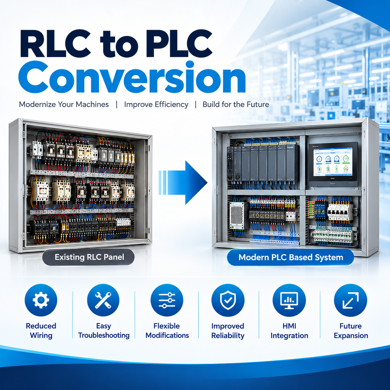 | Industrial Automation Solutions & System Integration RLC to PLC Conversion Services Upgrade Relay Logic Control to Smart PLC Automation with Ikodeautomation Ikodeautomation is one of the best RLC to PLC conversion and industrial... View product → |
Frequently asked questions
When is an existing relay machine worth converting to a PLC?
Convert it when the mechanics, frame, guarding and production process remain sound, while obsolete relays, timers or unavailable components threaten uptime. Do not use conversion to hide worn machinery or unresolved safety defects.
What evidence should you collect before starting relay logic conversion?
Collect cabinet photographs, wire numbers, terminal schedules, relay and timer part numbers, electrical drawings, I/O devices, machine sequences, fault histories and operator recovery procedures.
How do you preserve safety functions during a relay-to-PLC conversion?
Identify emergency stops, guard switches, overloads, pressure switches and other safety circuits before changing wiring. Define their safe state and retain safety-rated control where the risk assessment requires it.
What must a PLC conversion specification include?
Specify the PLC platform, I/O count, communication needs, timer and latch behaviour, fault recovery, test procedure, commissioning limits, drawings, software backups, training and spare-parts information.